
 English
 русский
 Español
 عربى
عربى
 Home / News / Industry News / DC Cable Size Calculator: How to Size DC Wiring Safely and Accurately for Any System
Industry News
DC Cable Size Calculator: How to Size DC Wiring Safely and Accurately for Any System
2026-08-28
Content
You have just finished wiring a 12 V off-grid solar circuit, and the inverter is already dropping out under heavy load. The battery reads 12.8 V, but the load terminals show 11.4 V. The usual suspect is not the charge controller or the battery; it is the DC cable, selected without a proper voltage drop calculation. This article explains how a DC cable size calculator works, which inputs matter most, and how to turn the result into a safe, practical cable choice for 12 V, 24 V and 48 V systems.
Why the Right DC Cable Size Matters
In a DC circuit, the cable has one invisible but critical job: keeping the supply voltage stable under load. Two physical effects govern the outcome — conductor resistance and heat. When a cable is too thin for the current, the conductor temperature rises. Higher temperature increases resistance, which adds more heat, pulls the load voltage down, and eventually degrades the insulation. This is why ampacity (current-carrying capacity) is the first check, and voltage drop is the second.
The practical symptoms appear quickly: lights dim when a motor starts, inverters trip on low input voltage, chargers run for longer, and electronics report brownouts. In an engine bay or battery compartment, an undersized cable can also become a fire risk. The chart below shows typical ampacity values for common metric copper cable sizes — useful as a starting point, but never sufficient on its own.
Reference ampacity for two loaded conductors, PVC insulation, 30°C ambient
How a DC Cable Size Calculator Works
Most DC cable size calculators use the same underlying formula:
A = (2 × I × L × ρ) ÷ Vdrop
where A is the conductor cross-section in mm², I is the load current in amperes, L is the one-way cable length in metres, ρ is copper resistivity (0.0172 Ω·mm²/m for commercial copper) and Vdrop is the allowable voltage drop expressed in volts.
The factor of 2 matters. DC power travels out through the positive conductor and returns through the negative conductor, so both conductors contribute equally to the total drop. A 5 m cable run between a battery and a load is a 10 m electrical circuit. Many hand calculations and simple online tools neglect this, and the resulting cable comes out one size too small.
Inputs you need to provide
- System voltage (12 V, 24 V, 48 V or a custom value)
- Load current in amperes, including start-up peaks for motors
- One-way cable run length in metres
- Target voltage drop, usually 3% for power circuits
- Installation type (free air, conduit, bundling and ambient temperature)
Choosing the voltage drop target
Three percent is the accepted maximum for most DC power distribution. For lighting and non-critical loads, 5% can be acceptable. For sensitive electronics and communication equipment, many engineers design to 2% or less. The lower the target, the larger the cable — and the cleaner the supply voltage your equipment sees.
The line chart below shows the practical impact. For a 10 A load on a 12 V system with a 3% voltage drop target, each cable size supports a certain maximum round-trip length before the drop exceeds the limit. A 2.5 mm² cable reaches only 2.6 m; a 16 mm² cable extends the same circuit to 16.7 m.
Maximum round-trip cable length, 12 V system, 10 A load, 3% voltage drop, copper conductor
DC Cable Size Reference Values
Once the calculator returns a required area, round up to the next standard size. The table below lists common metric sizes with reference ampacity and the voltage drop over a 5 m round-trip at 10 A. Use the computed area as a minimum, not as a final answer.
| Cable size (mm²) | Ampacity (A, PVC, 30°C) | Voltage drop per 5 m round-trip at 10 A (V) |
|---|---|---|
| 1.5 | 17.5 | 1.15 |
| 2.5 | 24 | 0.69 |
| 4 | 32 | 0.43 |
| 6 | 41 | 0.29 |
| 10 | 57 | 0.17 |
| 16 | 76 | 0.11 |
Rounding up by one size is usually cheap insurance. Re-wiring an entire installation later costs far more than the extra few cents per metre of a larger conductor.
Common DC Cable Sizing Mistakes
Even with a calculator, a few recurring mistakes push real installations into trouble.
- Using one-way length instead of round-trip length. Always multiply the physical distance by two.
- Sizing only by ampacity. A cable can carry the current comfortably but still produce a 7% voltage drop that makes equipment malfunction.
- Ignoring future loads. If the circuit will feed an additional load later, choose the larger size now.
- Forgetting ambient temperature and bundling. Ratings drop significantly in conduit, cable trays or warm engine compartments.
- Neglecting terminations and protection. Fuses, lugs and switch contacts all add resistance and heat.
Connection quality is where the neatest calculations fail. In a correctly sized DC circuit, the conductor typically accounts for about 65% of the total circuit resistance, terminals and lugs around 25%, and protection devices the remaining 10%. A loose or corroded terminal quickly overtakes the conductor as the main source of heat, even when the cable size is mathematically perfect.
Typical distribution of resistance in a terminated DC power circuit
- Conductor 65%
- Terminals 25%
- Protection 10%
Selecting the Right DC Cable for Your Environment
A size calculation selects the conductor area, but a real installation also demands the correct insulation, stranding and mechanical durability. Three common DC environments highlight what changes.
Automotive and engine-bay wiring
Vehicle wiring runs are short, tightly routed and exposed to heat, fuel and vibration. Thin-wall automotive cables with cross-linked or high-temperature insulation fit into harnesses without reducing the conductor cross-section. German-standard automotive wire is a practical starting point for OEM and aftermarket DC circuits, and our automotive wiring case studies show how stranded conductors survive years of flexing in an engine bay.
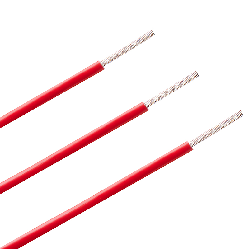 Wholesale German standard automotive wire Supplier, FactoryJiangsu Silver & Tin Thread Hi-temperature Wire and Cables Co., Ltd. is German standard automotive wire supplier and factory in China.We ...View Product →
Solar photovoltaic circuits
Solar arrays operate outdoors, under UV exposure, high roof temperatures and rain. Standard PVC insulation ages quickly in those conditions. Solar photovoltaic cable is manufactured with cross-linked insulation and better UV resistance, and its fine stranding keeps the conductor flexible through installation and thermal movement.
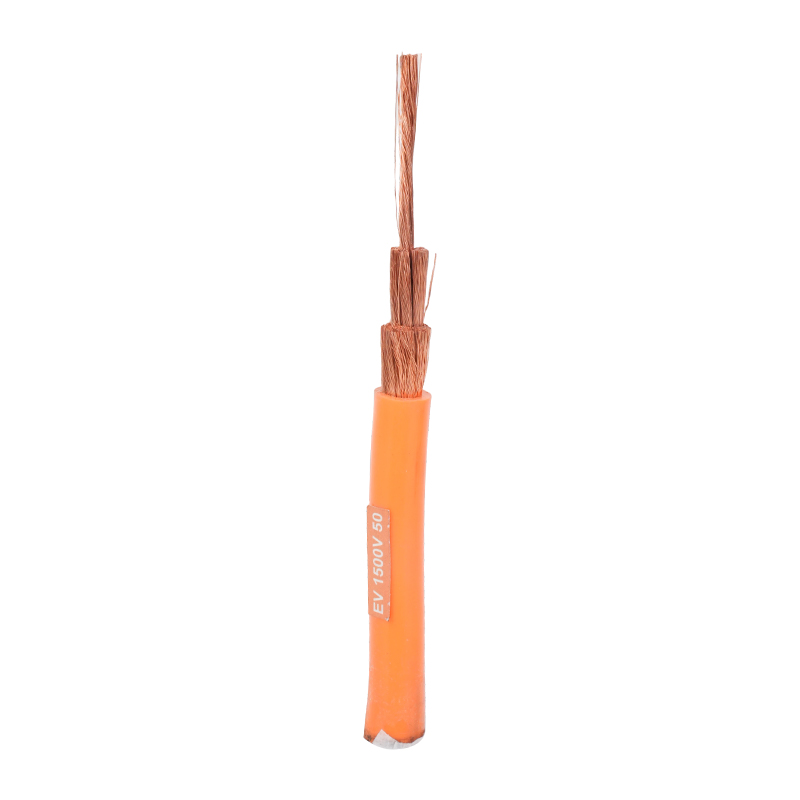 Custom Solar Photovoltaic Cables Manufacturer, Supplier - Jiangsu Silver & Tin TJiangsu Silver & Tin Thread Hi-temperature Wire and Cables Co., Ltd. is China custom Solar Photovoltaic Cables suppliers and company,Prod...View Product →
Battery energy storage systems
Battery banks combine high current with confined spaces and permanent connection to inverters and chargers. The cable needs to be flexible, flame-retardant and mechanically robust. We specify battery energy storage cable for these DC links, and the same logic applies to charger-to-battery and inverter supply runs. Our renewable energy applications page covers the surrounding decisions, including fuse placement and busbars.
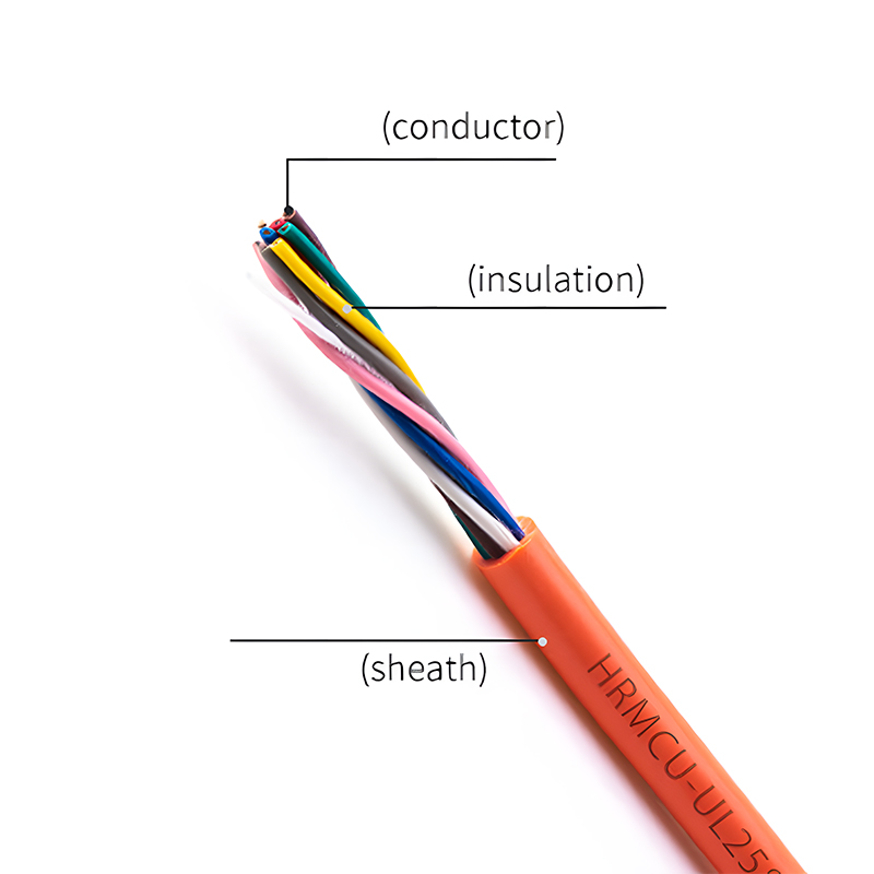 Custom Battery Energy Storage Cable Manufacturer, Supplier - Jiangsu Silver & TiJiangsu Silver & Tin Thread Hi-temperature Wire and Cables Co., Ltd. is China custom Battery Energy Storage Cable suppliers and company,M...View Product →
Frequently Asked Questions
How do I convert mm² to AWG?
Divide the area in mm² by 0.5067 and round up to the nearest larger AWG size. A 2.5 mm² conductor is close to 13 AWG; in practice most installs use 12 AWG because it is more widely available and provides a comfortable safety margin.
Can I use the same cable size for 12 V and 24 V systems?
No. At the same current and the same voltage drop percentage, a 24 V system tolerates approximately double the cable length of a 12 V system, because the allowable drop in volts is twice as large. Lower-voltage systems always require larger conductors for the same duty.
Does ambient temperature affect DC cable sizing?
Yes. Ampacity values are usually quoted at 30°C ambient. In engine bays or enclosed battery compartments, the current rating must be derated. A commonly used derating factor for PVC-insulated cable is 0.87 at 40°C and 0.71 at 50°C. If your calculator has no temperature input, apply these factors manually before comparing cable sizes.
What round-trip length can a 10 A load run on 12 V with a 3% drop?
With 2.5 mm² cable the limit is roughly 2.6 m; with 6 mm² it rises to about 6.3 m; with 16 mm² it reaches about 16.7 m. Exact values depend on copper grade and operating temperature.
A DC cable size calculator converts electrical conditions into a simple purchasing decision: enter the voltage, current, distance and allowable drop, then round up to the next standard size. The habit takes five minutes and prevents most of the voltage-related problems that show up after installation. Treat the reference values in this article as a baseline, respect the derating factors, and never underestimate the importance of clean, tight terminations.

-
Phone
+86-(0)21-6083 5889
+86 138 1238 0261 -
Email
export03@silvertincable.com
export@silvertincable.com -
Headquarter Address:
No. 20 Jianling Road, Zhangguo Community, Dainan Town, Xinghua City. Jiangsu Province China
-
Shanghai Branch:
Room 18A, West Building, Keji Jingcheng, No. 668 East Beijing Road. Huangpu District, Shanghai, China
Copyright © 2025 Jiangsu Silver& Tin Thread Hi-temperature Wire and Cables Co., Ltd. All Rights Reserved.
China industrial cable manufacturer Custom specialized wire & cable supplier