
 English
 русский
 Español
 عربى

 Home / News / Industry News / 3 Phase Motor Cable Size Chart: A Practical Selection Guide with Tables

Industry News
3 Phase Motor Cable Size Chart: A Practical Selection Guide with Tables
2026-09-04
Content
Your maintenance team is standing in front of a supplier's binder with a 3 phase motor cable size chart. The motor nameplate says 30 kW, 400 V, and the chart says 16 mm² copper cable. Before you release that purchase order, ask one simple question: was that table built for your actual installation conditions? In most cases the answer is no. A chart is a screening tool, not a design document. It can save time, but it will not give you a safe, code-compliant result unless you first verify three things: full load current, derating factors, and voltage drop.
How a 3 Phase Motor Cable Size Chart Works
A 3 phase motor cable size chart typically starts with motor output power and shows full load current for a given voltage. It then lists a recommended conductor cross section in mm² or AWG. Some charts also add breaker size, starter size, or conduit size. These tables are useful for quick estimates in standard conditions: 30°C ambient, copper conductor, PVC insulation, cable in free air or a single conduit.
The chart is not wrong, but it is incomplete. The actual ampacity of a conductor depends on installation method, ambient temperature, number of loaded conductors, and insulation rating. A cable that works in free air may be too small when it is routed through a thermally insulated wall or bundled with other cables. That is why engineers should use a table as a starting point and then apply the correction factors from the relevant standard, such as IEC 60364-5-52, BS 7671, or NEC 2023.
| Motor Output (kW) | FLA @ 400 V (A) | Recommended Cu Size (mm²) | FLA @ 480 V (A) | Recommended Cu Size (mm²) |
|---|---|---|---|---|
| 5.5 | 11 | 2.5 | 9 | 2.5 |
| 7.5 | 15 | 4 | 12 | 4 |
| 11 | 23 | 6 | 19 | 6 |
| 15 | 30 | 10 | 25 | 10 |
| 22 | 42 | 16 | 35 | 16 |
| 30 | 51 | 16 | 42 | 16 |
| 45 | 85 | 35 | 70 | 35 |
The Main Factors That Change Your Cable Choice
Derating is the most common reason why a chart-based selection fails in practice. The baseline ampacity of a conductor changes when the ambient temperature rises above 30°C, when more than three current-carrying conductors are bunched, and when the cable is installed in thermally insulated walls. A 16 mm² cable rated at 70 A in free air may only be allowed to carry around 55 A in a conduit with other cables. A 30 kW motor at 400 V draws 51 A under full load, and that room disappears quickly.
For a motor circuit, many standards require the branch-circuit conductors to have an ampacity of at least 125% of the motor's full load current. This is a practical safety margin that covers normal starting current and protects the conductor in the event of a stalled rotor. When you add that margin to derating, the recommended size often goes up by one or two steps.
How to Calculate Voltage Drop and Why It Matters
Voltage drop is the second gate for a correct cable size. The motor torque and current draw are sensitive to voltage at the terminals. A long cable can cause the motor to run hotter, reduce efficiency, and make contactors or starters drop out. For a three-phase circuit, the approximate voltage drop is calculated as:
VD = 1.732 × I × L × (R × cos phi + X × sin phi) / 1000
where I is full load current in amps, L is cable length in metres, R is AC resistance in ohm per km, and X is reactance in ohm per km. For cable sizes up to 35 mm², R dominates, so the reactance term can often be ignored for a quick check. Most designers accept a maximum voltage drop of 5% from the supply point to the motor terminals.
Example: a 30 kW motor at 400 V draws 51 A. With 16 mm² copper cable, R is approximately 1.15 Ω/km. At a length of 100 m and a power factor of 0.85, the voltage drop is about 1.8 V, which is only 0.45% of 400 V. At 300 m, the same cable gives about 5.4 V, or 1.35%, which is still acceptable. At 800 m, the drop becomes about 14.4 V, or 3.6%, and the cable may still pass, but the motor will feel the loss. A designer would usually increase to 25 mm² or more for a long run to keep losses low and improve starting performance.
Voltage drop
Ambient temperature
Installation method
Starting current
Factors that often force an increase in the cable cross section.
Real-World Selection Examples
Let's apply the principles to three common situations.
Case 1: 30 kW motor, 400 V, 80 m run in metal conduit. Full load current is 51 A. With 125% margin, the design current is about 64 A. A 16 mm² cable in conduit has a reduced ampacity, so use 25 mm². The voltage drop will be about 1.1% at 80 m, which is within the 5% limit.
Case 2: 7.5 kW motor, 480 V, 200 m run in free air. FLA is around 12 A. The current is small, but the length is long. A 2.5 mm² cable would give a voltage drop of roughly 6.8%, which is too high. In this case, the cable must be increased to 4 mm² or even 6 mm² to respect the 5% rule.
Case 3: VFD-driven 30 kW motor, 400 V, 30 m run. The motor current is still 51 A, but the VFD output is a PWM waveform. The cable needs shielding to prevent reflected wave damage and common-mode noise. The answer is a screened flexible cable, often 16 mm² or 25 mm² depending on the cable type and installation.
Demanding Environments and Special Cable Requirements
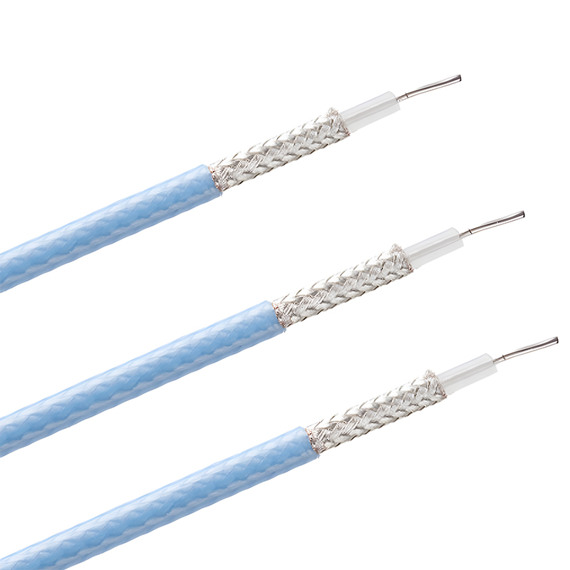
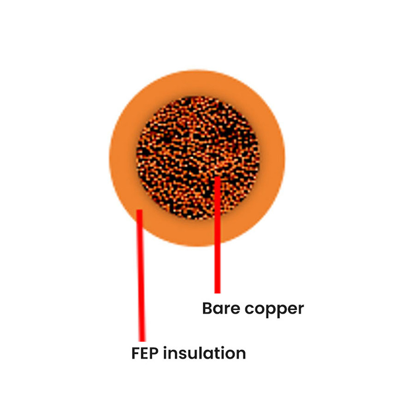
High temperature is the most obvious condition that makes a standard cable size chart useless. A motor in a furnace room or metallurgical plant may see ambient temperatures above 60°C. Standard PVC insulation will be derated so heavily that a larger copper conductor is required. A better solution is to choose a cable with fluoroplastic or silicone insulation rated for 180°C or higher. For these duties, the manufacturer offers a range of teflon wire and other high-temperature options.
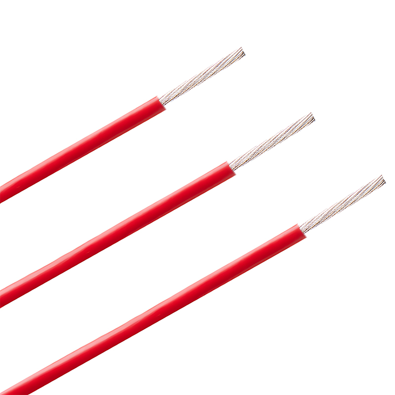 High-Temperature Cable Options for Motor and Furnace ApplicationsThese cables with FEP, PFA, PTFE, or silicone insulation are rated for 180°C or higher, making them suitable for motor windings in furnace rooms where ambient heat exceeds standard PVC limits.View Product →
Another situation is the short connection between a motor terminal box and its associated equipment. This is the classic use case for a motor lead wire: it is flexible, oil-resistant, and rated for the current and temperature of the motor winding. Choosing the wrong lead wire is a common cause of early wiring failure because vibration and thermal cycling are not captured in a cable size chart.
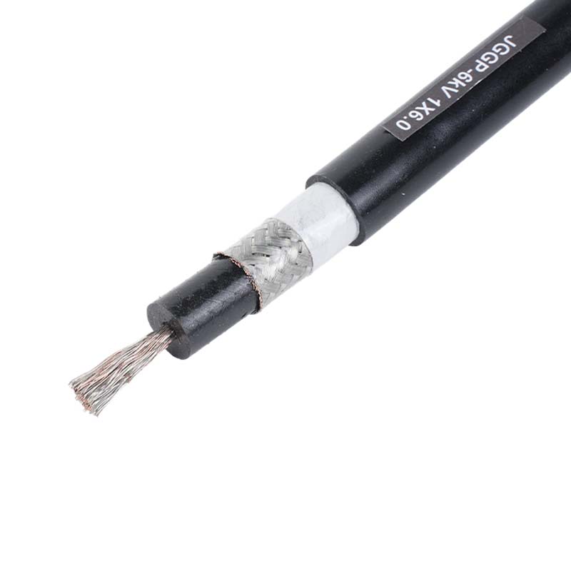 Flexible Silicone Motor Lead Wire for High-Temperature EnvironmentsDesigned for motor terminal connections, this lead wire features ultra-fine tinned copper conductors and silicone insulation, offering flexibility, oil resistance, and stable performance in high-temperature, vibration-prone settings.View Product →
For motors installed on vehicles, in automated production lines, or in other mobile equipment, cable construction becomes more important than just ampacity. Multicore automotive cables comply with German or Japanese standards and are designed for cold flexing, oil resistance, and small bending radii. In these applications, electrical engineers still start with a current-based size, but the final decision is heavily influenced by the manufacturing environment.
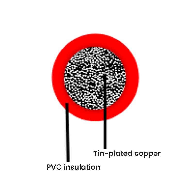 Automotive Cables for Mobile Equipment and Harsh ConditionsThese multicore automotive cables meet German standards and are built for cold flexing, oil resistance, and tight bending radii, making them ideal for motors in vehicles and automated production lines.View Product →
Similar reasoning applies to wind turbines and solar tracking systems, where motors are exposed to temperature swings and mechanical stress. The cable selection for these installations should be considered together with the overall renewable energy industry requirements. This is another area where a supplier with narrow product focus may not be able to provide a single source for the complete cable chain.
Frequently Asked Questions
Can I use a 3 phase motor cable size chart as a final design guide?
No. A chart is a screening tool. Use it to get a starting point, then verify ampacity after applying derating factors and check voltage drop for the actual run length.
Does cable length affect the size?
Yes. Longer cables increase voltage drop. If the run is long, you may need a larger conductor than the chart suggests.
Why does a VFD-driven motor need a different cable size?
VFD output is a high-frequency PWM waveform. Standard cable may experience reflected wave voltage spikes and radiated noise. Shielded, low-inductance cable with a correct surge impedance is preferred.
Is a larger cable always better?
Not always. A large cable costs more, is harder to terminate, and may not fit in the terminal box. Select the smallest size that meets ampacity, voltage drop, and short-circuit protection requirements.
What standard should the size chart follow?
Use a standard that matches your country and installation type. IEC 60364-5-52 and BS 7671 are common for many regions, while NEC 2023 applies in the United States and some other markets.
Final Checklist Before Ordering
- Confirm the full load current from the motor nameplate.
- Add 125% margin if the circuit is protected by NEC rules.
- Determine the installation method and apply derating factors.
- Calculate voltage drop over the intended cable length.
- Check whether the environment requires a special insulation material.
- Match the conductor material and cross section with the terminal rating.

-
Phone
+86-(0)21-6083 5889
+86 138 1238 0261 -
Email
export03@silvertincable.com
export@silvertincable.com -
Headquarter Address:
No. 20 Jianling Road, Zhangguo Community, Dainan Town, Xinghua City. Jiangsu Province China
-
Shanghai Branch:
Room 18A, West Building, Keji Jingcheng, No. 668 East Beijing Road. Huangpu District, Shanghai, China
Copyright © 2025 Jiangsu Silver& Tin Thread Hi-temperature Wire and Cables Co., Ltd. All Rights Reserved.
China industrial cable manufacturer Custom specialized wire & cable supplier