
 English
 русский
 Español
 عربى

 Home / News / Industry News / Cable Size Calculation: How to Select the Right Conductor Cross-Section

Industry News
Cable Size Calculation: How to Select the Right Conductor Cross-Section
2026-09-11
Content
- 1 Step 1: Determine the Design Current and One-Way Route Length
- 2 Step 2: Use the Voltage-Drop Formula to Find a Starting Cross-Section
- 3 Step 3: Check Voltage Drop With the Real Installation Length
- 4 Step 4: Multiply the Derating Factors
- 5 Worked Example: Sizing a 48 V DC Feeder
- 6 High-Temperature Areas Change the Limiting Component
- 7 Solar and Battery Circuits Need a DC-Specific Check
- 8 Automotive Harnesses Tighten the Voltage Budget
- 9 Frequently Asked Questions
Every cable failure I have had to trace through an industrial plant could have been prevented at the drawing board. Cable size calculation is not about picking a gauge from an online chart. It is a four-step process that balances load current, conductor resistance, voltage drop, ambient conditions, and the physical route of the cable. The most important number is not always the cable's ampacity; on a long run, voltage drop usually decides the cross-section.
Use this order: estimate the design current, calculate the minimum conductor area for voltage drop, verify ampacity after derating factors, then choose a cable with insulation and voltage rating suited to the environment.
Step 1: Determine the Design Current and One-Way Route Length
The phrase "design current" is deliberately different from nameplate current. A motor draws a starting current that can be several times its full-load current, a battery charger has a bulk and absorption phase, and a PV string runs close to its short-circuit current on bright days. Use the value that the cable will carry continuously after demand factors are applied.
- Continuous loads should use the full rated current unless the local code allows a demand factor.
- Voltage-sensitive equipment such as PLCs, servo drives, and instrumentation may need a tighter limit than the general power allowance.
- Measure the one-way route length in meters, including vertical runs and allowances for bends. This length appears in every formula, so a small routing error becomes a hidden voltage-drop problem.
Step 2: Use the Voltage-Drop Formula to Find a Starting Cross-Section
Conductor resistance is the main variable that controls cable size. For DC and single-phase circuits with negligible reactance, the minimum conductor area can be estimated as:
A = (2 × L × I × ρ) / Vd
For balanced three-phase line-to-line circuits, use:
A = (√3 × L × I × ρ × cosφ) / Vd
Where L is one-way length in meters, I is design current in amperes, ρ is conductor resistivity in Ω·mm²/m at the expected operating temperature, Vd is the allowable voltage drop in volts, and A is the minimum conductor cross-section in mm². The resistivity value matters more than people expect; copper at 70°C is not the same as copper at 20°C.
| Conductor material | ρ at 20°C (Ω·mm²/m) | Approx. ρ at 50°C | Approx. ρ at 70°C |
|---|---|---|---|
| Copper | 0.0172 | 0.0181 | 0.0206 |
| Aluminium | 0.0282 | 0.0297 | 0.0339 |
Step 3: Check Voltage Drop With the Real Installation Length
Voltage drop is a distance problem. A conductor that passes the ampacity check can still leave a motor terminal far below its rated voltage if the run is long or the circuit is lightly loaded but poorly sized. The chart below shows how voltage drop grows with current for three common copper cross-sections on a 20 m single-phase circuit.
A 1.5 mm² conductor may carry 16 A thermally in free air, but the same conductor at 25 A over 20 m loses 11.5 V. If this is a 230 V circuit that is still a visible drop; if it is a 24 V control circuit, the equipment may not run at all.
| Circuit type | Maximum voltage drop |
|---|---|
| Lighting circuits | 3% |
| Power circuits | 5% |
| DC PV and battery feeds | 1–3% recommended |
Step 4: Multiply the Derating Factors
Catalog ampacity is rarely equal to installed ampacity. Grouping, ambient temperature, solar radiation, conduit fill, and installation method each reduce the cable's ability to shed heat. These factors multiply, so a circuit that seems fine in a table may fail when six cables share one tray.
| Ambient temperature (°C) | Correction factor |
|---|---|
| 25 | 1.03 |
| 30 | 1.00 |
| 35 | 0.94 |
| 40 | 0.87 |
| 45 | 0.79 |
| 50 | 0.71 |
Combined derating is where engineering experience matters. A 0.94 ambient factor and a 0.85 grouping factor do not add; they multiply to 0.80, and another 0.93 for direct sunlight gives 0.74. A 16 A design current then requires a cable with a table ampacity of at least 21.6 A. This is the step that prevents hot terminals and premature insulation failure.
- Voltage drop overlooked 35%
- Ambient derating ignored 28%
- Load growth underestimated 22%
- Wrong installation method 15%
Worked Example: Sizing a 48 V DC Feeder
Suppose a 48 V DC hoist power feeder runs 20 m one way, carries a design current of 20 A, and is expected to operate with a conductor temperature near 50°C. Using copper with ρ = 0.0181 Ω·mm²/m, the minimum cross-section for a 3% voltage-drop limit is:
A = (2 × 20 × 20 × 0.0181) / (0.03 × 48) = 10.06 mm²
The calculated value sits slightly above 10 mm², so the correct commercial choice is 16 mm². If the owner accepts a 5% voltage-drop limit, the maximum drop becomes 2.40 V and the calculated area is 6.03 mm², leading to a 6 mm² cable after an ampacity check. The same route, same load, and two different voltage tolerances give two different cables.
| Allowed voltage drop | Maximum drop (V) | Minimum calculated area (mm²) | Nearest standard metric size |
|---|---|---|---|
| 3% | 1.44 | 10.06 | 16 mm² |
| 5% | 2.40 | 6.03 | 6 mm² |
High-Temperature Areas Change the Limiting Component
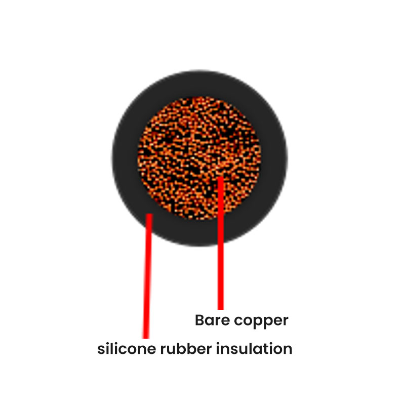
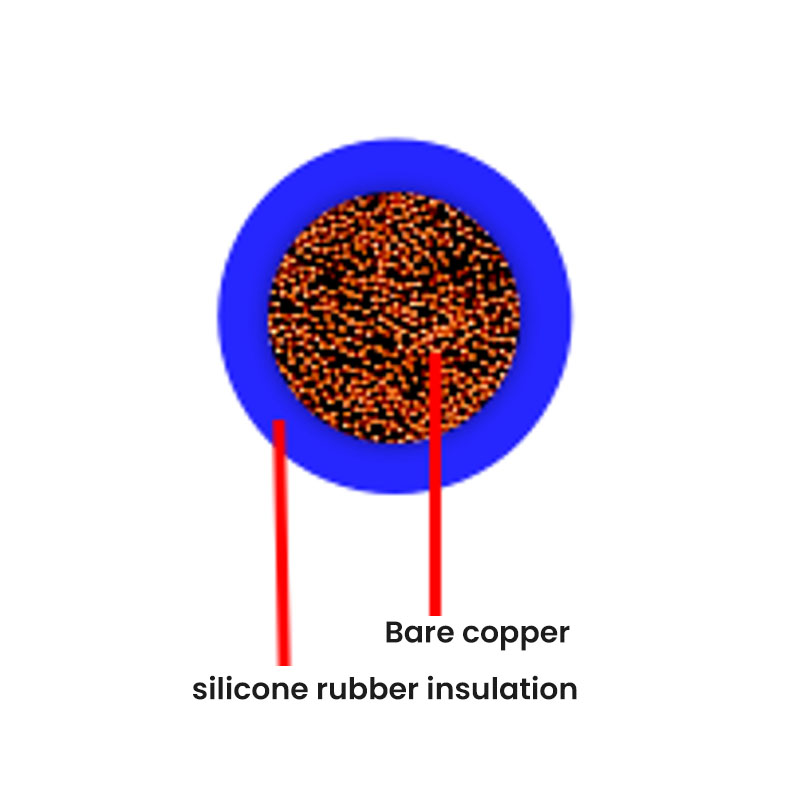
High ambient temperature raises conductor resistance and reduces insulation service life. A circuit routed beside a process pipe may pass the voltage-drop calculation but fail because the insulation cannot survive the enclosure temperature. In this situation, the cable type is as important as the cross-section. Silicone-rubber insulated cable is a common solution in ovens, hot panels, motor compartments, and near autoclaves.
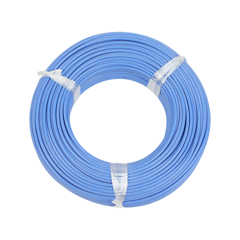 Silicone Rubber Insulated Wire for High-Temperature EnvironmentsThis product group covers silicone rubber insulated cables designed for heat-exposed locations such as ovens, motor compartments, and process piping. Review versions like AGR, YGZ, and shielded types to match temperature and abrasion needs.View Product →
Solar and Battery Circuits Need a DC-Specific Check
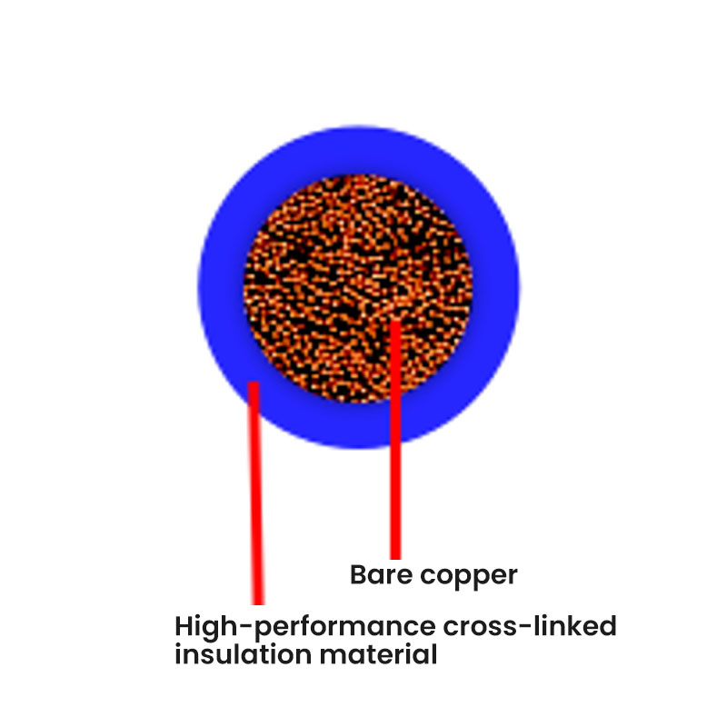
Photovoltaic strings are different from general power circuits because they run on DC, operate outdoors, and often carry current for long hours. The cable should be sized for at least 1.25 × Isc, and the voltage drop between combiner box and inverter should stay below 3% wherever possible. Battery storage adds a short-circuit duty that a normal ampacity table does not cover. The right product group needs double insulation, UV resistance, and stable conductor temperature. See how these requirements are handled across our renewable energy cable applications.
renewable energy cable applications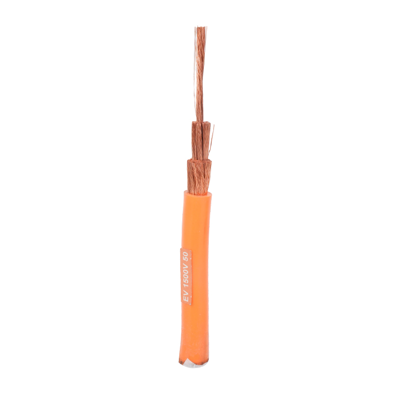 Solar Photovoltaic DC Cable with UV-Resistant Cross-Linked InsulationEngineered for outdoor PV systems, this cable handles DC power at 1.5 kV and resists UV, ozone, and harsh weather. Its flexible conductor and flame-retardant sheath suit module-to-inverter connections in rooftop and utility-scale arrays.View Product →
Automotive Harnesses Tighten the Voltage Budget
Vehicle wiring is short, but the allowable voltage drop is extremely tight. A 0.5 V drop in a 12 V auxiliary feed is about 4% of the system voltage, and the underhood ambient can exceed 100°C. The cable size calculation still starts with the same resistance formula, but the final choice depends on strand flexibility, insulation grade, and the standard the harness must meet.
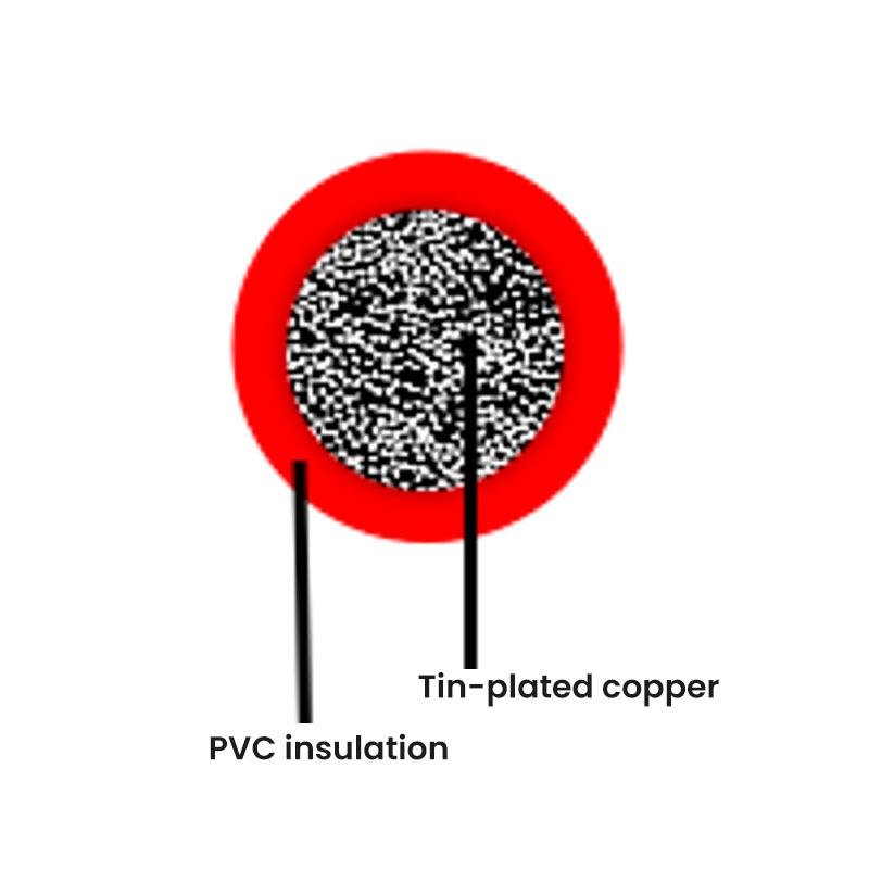 German Standard Thin-Wall Automotive Single-Core CableThis range includes FLRY, FLR9Y, and ultra-thin wall options that meet German harness standards. They balance tight voltage-drop limits with flexibility and high-temperature tolerance, making them suitable for underhood and auxiliary vehicle circuits.View Product →
Frequently Asked Questions
What is the simplest cable size calculation formula?
For DC and single-phase resistive loads, use A = (2 × L × I × ρ) / Vd. It gives a minimum conductor cross-section based on voltage drop and is a good starting point for any low-voltage circuit.
Why do two cable calculators give different sizes?
Because they use different assumptions. Ambient temperature, installation method, grouping, conductor material, insulation type, and the allowed voltage-drop limit all affect the result. A calculator that ignores derating factors will always give a smaller and less reliable cable.
Should I calculate voltage drop first or ampacity first?
Start with voltage drop. On long runs it almost always sets the minimum cross-section. Then verify that the chosen cable still has enough ampacity after derating factors. If the ampacity is too low, increase the cross-section and repeat the voltage-drop check.
What is the most common cable sizing mistake?
Ignoring combined derating. A cable that passes in a single-core free-air table can fail when it is bundled with other cables in a hot tray. The factors multiply, and the effective current capacity can be 25–30% lower than the table value.
A cable size calculation is not a one-time administrative task. It is the first layer of reliability for the whole installation. If the load changes, the route is extended, or the ambient temperature rises, the cable size has to be checked again. That is why experienced engineers treat the calculation as a living specification rather than a written number.
When these principles are ignored on real production lines, the cost shows up as voltage complaints, burnt terminals, and machine downtime. Our industrial machinery case studies show the same root-cause logic applied to cable-related failures in automated equipment.
industrial machinery case studies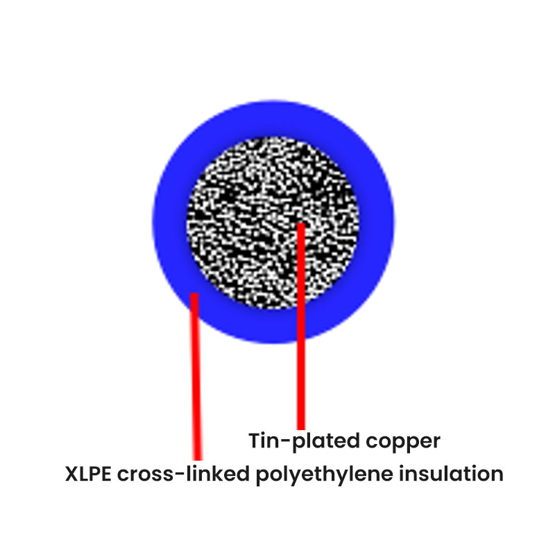

-
Phone
+86-(0)21-6083 5889
+86 138 1238 0261 -
Email
export03@silvertincable.com
export@silvertincable.com -
Headquarter Address:
No. 20 Jianling Road, Zhangguo Community, Dainan Town, Xinghua City. Jiangsu Province China
-
Shanghai Branch:
Room 18A, West Building, Keji Jingcheng, No. 668 East Beijing Road. Huangpu District, Shanghai, China
Copyright © 2025 Jiangsu Silver& Tin Thread Hi-temperature Wire and Cables Co., Ltd. All Rights Reserved.
China industrial cable manufacturer Custom specialized wire & cable supplier